
History
More Than 25 Years of Custom British Crankshafts
An autobiographical account of the business of ED G Cranks and the building and testing offset, and other custom, crankshafts for classic British twins since 1999.
Initially the business began as a word-of-mouth business among fellow members of the Canadian Vintage Motorcycle Group before becoming a web-based business in 2004. As of March 2018 the business has manufactured about 80 offset crankshafts including about 20 that are currently on-hand for future sale including 12 partially machined stroker crankshafts for Triumph twins.
I should mention that I don’t mind sharing everything I know about making crankshafts and camshafts. The machining, welding, heat treating, grinding and balancing information has taken many years to learn. Even if I told someone how to do it they would still make many of the same expensive mistakes that I made but also learn a lot.
From the beginning I have always recognized that the market was limited to old, cheap guys that are not riding as much as they did. When we were younger it was fine riding a vibrating, parts-losing British bike when it was the only thing that was available before the big Japanese bikes arrived in 1969.
 At this point, on a cold but sunny March day, I believe ED G Cranks the only manufacturer of crankshafts for vintage British twins that are welded, ground, heat-treated and balanced to individual customer requirements. My crankshafts can be installed in a British twin, in most cases, without modification. In most cases these crankshafts are 4 to 5 pounds lighter than a stock British twin crankshaft and are slightly smaller in diameter so that they have less inertial weight.
55 Years Of Offset Crankshafts
The idea of building an offset crankshaft first caught my attention in a Classic Bike article in April 1994 about the writings of Phil Irving, the famous designer and builder of the Vincent motorcycle. He proposed, in a British motorcycle magazine in the early sixties, that the best British twin should be built using a crank with the journals offset by 760.
He proposed that with a 760 offset one piston would be in the middle of the stroke, traveling at maximum speed in one barrel while the other piston would be at either TDC or BDC in the other bore. His thinking, based on the 82mm stroke of a Triumph twin, and similar strokes of BSA A10 twin and Norton twins, was that with one piston moving at maximum speed in one barrel that the ‘static’ piston in the other barrel would be assisted through TDC, or BDC, at a faster rate. Phil Irving also noted that this effect could be partially achieved with a crankshaft using a 900 offset spacing and have the advantage of having perfect primary balance. My simplification of everything that he wrote is enough for this article.
The perfect primary balance of a 900 offset has a long history in the automotive world with Ford’s first V-8 engine and Cadillac’s straight-eight engine of 1908. This straight-engine was said to be the smoothest automotive engine ever built but was costly to build because the ignition system used four separate magnetos making it extremely expensive and unreliable. In modern times all Triumph twins are now built with a 900 degree offset (or 2700). Yamaha has also built many 270o twins including the recent MT-07 700c twin (2013) and the TRX850 from 1996 to 2000. The Yamaha R1 is built with a 4 cylinder engine with 900 offset between throws as well.

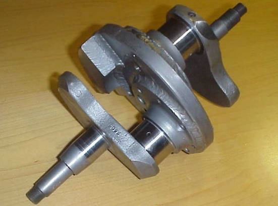
Figure 1 – Two halves of a Triumph three-piece crankshaft. A new flywheel is easily made for this type of crank.
Going back to the 760 offset engine I noted another article in Classic Bike about an Australian racer that built a 760 crankshaft from a three-piece pre-unit crankshaft. He noted that his motorcycle was smooth and fast and did not require a heavy flywheel making the motorcycle accelerate faster.
Another article about Dick Wilson, of East Bethany, New York, in the Triumph Owners International Club magazine described how he built a 760 offset crankshaft with more detail describing how he drilled additional holes in the flywheel of a three-piece pre-unit Triumph crankshaft then rode the motorcycle to California. The only draw-back he noted was that he was not sure about the strength of this assembly using 12 bolts through the thin sections of a cast iron flywheel.
It was after reading these articles that I decided that welding was better than drilling a bunch of holes.
Tooling
After looking at all the articles on offset crankshafts, including others about BSA crankshafts used for sidecar racing, I determined to build my own. Noting previous information about Dick Wilson’s concerns about the weakness of a bolted assembly I decided the only way to build this crankshaft was to weld it. If I was going to weld this crankshaft I need a fixture to hold the crankshaft journals in-line. This also allows the welder to rotate the crankshaft to get at all sides of the crankshaft and the flywheel. As a former tool-maker, wood worker and CNC programmer, I knew how to make everything I needed myself or who could do the work that I could not such as welding, crankshaft grinding and heat treating.
Casting is a simple process. Making a pattern similar to what I needed, with no internal holes, or cores, is even easier. I glued and screwed a bunch of wood together making sure I had generous draft angles, to allow easy removal of the pattern from the casting sand. Wood filler was used to ensure there were no sharp radius’ in the inner corners as well as reducing stress. A lot of hand sanding was done to prevent the sand from sticking to the pattern. Lake Foundry, in Grimsby, Ontario did the casting and stress-relieving using Class 45 cast iron. This iron alloy remains stable when heated up to temperatures of 15000F which was important because I initially thought the crank would have to be stress-relieved in the fixture after welding.
Lake Foundry also handled the line boring of a 1.500” diameter hole through both webs of the fixture. While building the fixture I planned on building BSA, Norton, Matchless/AJS, Royal Enfield and Triumph twin crankshafts. The ability to mount different crankshafts in the fixture determined the width of the webs and the use of collets to hold each type of crankshaft.
The last tooling component that had to be made were various stops that could be used to set each journal at the right offset in the fixture. These were important because of the different big end journal sizes; 1.4375” (Triumph 500), 1.625” (Triumph 650 and 750), 1.6875” (BSA) and 1.750” (Norton). Main bearing sizes also vary from 1.125” to 30mm and to 1.5”


Figure 2 – Fixture (left)
Figure 3 – Fixture today with stops (above)
The process starts with obtaining a good donor crankshaft. These cranks must be straight, still be at standard big end journal size, have no damaged threads, splines or key ways and crankshaft ends that are not mushroomed by the previous owner’s hammer. It is easy to find BSA A65 and one-piece Triumph cranks in this condition because there are so many of them and they are made from forged materials. BSA A10 cranks are even harder but still available. The stock flywheel is removed and thrown away – a few are kept for sale but most have holes drilled in them from previous balancing attempts by the DPO (dreaded previous owner).
Norton crankshafts are a special case. Every Norton crankshaft that I have ever found has been bent in some way, the journals are no longer stock size and one end or both ends are mushroomed. These cranks are also made from cast alloy steel where BSA & Triumph cranks are forged. Norton cranks are rare enough that I have to accept cranks that are undersize and have them welded back up to stock size. At the date this account was written I have 10 Norton cranks that have been modified to become Triumph stroker cranks but when they are gone, they are gone.
A summary of my process follows:
-

Figure 4 – Crankshaft sawing
Check crankshaft for straightness and fix if possible (especially Norton cranks).
- Remove flywheels (BSA and Triumph) or separate from central flywheel (Norton).
- Machine timing side journal to Customer specification (BSA only).
- Saw crankshaft in half (BSA and Triumph), remove sludge trap and clean all oil ways.
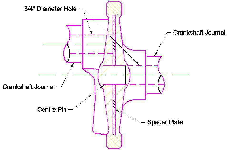
- Machine surfaces of crankshaft ends and bore ¾” hole in centre (BSA and Triumph) and remove sludge traps. An oil filter is required with all offset crankshafts.
-

Figure 5 – Spacer plate
Machine spacer plate from 4140 alloy steel with oil gallery channels (BSA and Triumph) Norton flywheels include 2” diameter cavities on each side with an oil hole drilled between each cavity
- Machine flywheels using 4140 alloy steel for each crankshaft type. BSA and Triumph cranks use a simple ring while a Norton flywheel has two offset cavities that are joined by a drilled oil hole.
7a – BSA and Triumph: Set up crankshaft in fixture with stops and tack weld. Adjust crankshaft so that it still rotates smoothly in the fixture then weld all around with H13 alloy welding rod. Crankshaft halves are positioned so that the timing side is the normal and the drive side is moved 900 behind the timing side in direction of crankshaft rotation.
or
7b – Drill holes in Norton crank halves using drill jig and pin together using central ½” pin and 3/16” split roll pins. Mount in fixture and weld all around crankshaft and all holes using H13 alloy rod. Similar to what is noted above the drive side is positioned 900 behind the timing side in the direction of crankshaft rotation. - Machine welded center to create mounting for flywheel (BSA and Triumph).
- Weld flywheel while rotating crankshaft in fixture using H13 alloy rod (BSA and Triumph).
- Grind crankshaft and straighten as required.

")
- Heat treat crankshaft using nitriding process. This process is done in an ammonia gas environment at 9350F for a total of 36 hours; 12 hours to bring parts to soak temperature, 12 hours at soak temperature of 9350F and 12 hours of cooling to return to room temperature. The nitriding process hardens the crankshaft surface to a depth of .015”, reduces the crankshaft flexibility (more power?) and stress-relieves the crankshaft. This process can be done faster but I learned through experience that it warps the crankshaft.
- Polish journals to specified size (stock or .010” undersize only).
- Machine counterweights to suit crankshaft type.
- Balance crankshaft using counterweighs a long with connecting rod weight information and piston weight with wrist pin, rings and cir-clips. Balancing is done rotationally and side-to-side to reduce the effect of the rocking couple inherent in an offset crankshaft.


It should be noted that there is a lot of driving around between the machinists, welders, crankshaft grinders, heat treaters and balancers. Over the years of doing this I have used the following services:
- Machining: Gulesserian Precision Machine, Wideline Machine (Scarborough) and N. A, Yorke (Etobicoke). N. A. Yorke is no longer in business – they did most of my stroker flywheels on their CNC equipment
- Welding: Toolweld Enterprises and Precise Welding (Scarborough).
- Crankshaft Grinding: Canadian Chrome Plating & Crankshaft Grinding (Concord)
- Heat Treating: Atlantic Heat Treating (Ajax)
- Balancing: D. Garland & Son (Scarborough) and SEM Powertrain (Pickering).
I have tried using other services over the years, to cut down on the driving, but have not found anyone that could do the work at the right price and the right quality.
First Crankshafts and Test Rides
My first offset crankshaft Triumph was completed and on the road in the summer of 1999. This is a custom bike with a Yamaha RZ500 front end, Honda 750 front wheel, Nikasil 750cc barrels, a belt drive, many custom titanium and aluminum parts to reduce weight, a custom fiberglass seat and a 1999 Suzuki Katana tail light which has to be the most sexy tail light shape ever made.
The custom exhaust system and so-called muffler was made by Hindle back at a time when they would do custom one-off work. A Tony Hayward belt drive helps make the bike as smooth as possible along with a balanced clutch. Note how the Trophy-style pipes go inside the frame making the motorcycle narrower. Honda GL1000 instruments are used with the front wheel speedo drive and the tachometer was the same 2:1 ratio as a stock Triumph tachometer.

1970 Triumph Trophy with 750cc Nikasil barrels and single carb
With flangeless alloy wheels and other modifications this bike weighs less than 320 pounds dry. The fairing is from a 1981 Yamaha Seca 550; I removed the bubbles on each side where the horns normally site. The bike handles like a light 250 but with the fairing can cruise at an average of 140 klics (90 mph) until you run low on gas. That’s a trip on the 401 highway from Toronto to Belleville on a small 2-1/2 galloon Triumph tank.
This bike is loud reminding me of the sound of open exhaust V8 engines at the long-gone Pinecrest Speedway in suburban Toronto I named the bike Pinecrest after that infamous place.
I have run this bike, as built, for 20 years. Over those years of regular riding I have only lost one bolt (a head steady mount) and cracked the fiberglass seat (two-up riding on a café-style seat).
The first ride was a shock. I could hear the bike but it wound up quickly like a Japanese four and was as smooth. This was only on a local street so it took patience, and a long break-in period, before I got on the highway. The bike remained as smooth as an air-head BMW until about 4500 rpm. At that point vibration sets in but still less, at that speed, then a typical British twin. I was to later learn that the 66% balance factor I used was more suitable for riding below 4500 rpm. It’s still a great bike but could be better.
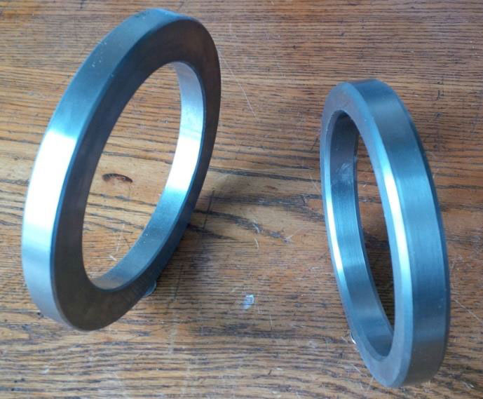
BSA & Triumph flywheel options
This first crank was an important learning experience both on how to build and in the best balance factor to use. I used the stock flywheel and quickly learned it was easier to machine my own. This saved my huge amounts of money with welding and balancing. Originally I made cranks using two separate cranks that were sawn, machined then and welded together.
I later learned how to saw a single crank apart and use a spacer for oil galleries and weld it all together. The welded crank was then machined to slip on a new flywheel, a ring that is 5/8” wide and 6” in diameter to fit the crank the same way a stock crankshaft was fit except that it is welded in place rather than bolted in place.
The performance was also notable.
After carefully breaking the engine in, over 1500 kilometres, I took the bike to the June 1999 CVMG Annual Rally. On the road run I found I was keeping up with, and accelerating as fast as Norton Commando 850s with this first bike. With the second bike, a Triumph 650, with the lighter machined flywheel, I found it could accelerate at the same rate as the 750 but this bike was smoother right up to red line with its 50% balance factor. This bike has the same Megacycle camshaft profile as the 750 but uses the stock chain primary drive.
I built the first ignition system for the 750 using two Boyer-Bransden ignition systems with a modified stator using 4 pickups. Each pair of pick-ups is connect to a single coil and one spark plug. With two ignition system ‘black boxes’ a fully charged battery is mandatory. I converted this to a single pickup system with a modified rotor but still think the dual ignition system is better in spite of it being harder to start. Both bikes now run TriSpark ignition systems which provide a stronger spark and the bikes are easier to start even if the battery charge is low.
Balancing
The first crankshaft was built using a stock Triumph flywheel that was machined to match the balance factor that I specified. Various chunks of metal were carved out of it and holes were drilled into the cast iron flywheel that was welded to the crankshaft using stainless steel welding rod. After this crankshaft was done the balancers (D. Garland & Son) suggested I machine my own flywheel and supply them with material for counterweights for them to install.
With the first crankshaft I had no idea what balance factor to use. None of the articles I saw mentioned the balance factor that was used and any information I could find in magazines at the time did not include this information. Since the web was not what it is today (in 1999) I had to guess. I chose 66% because any information I could find noted balance factors from 40% (an all-out racing Norton) to 77%. I eventually found, as I built other cranks, and from getting feedback from customers that 50% works best for road bikes, 45% for long-track race bikes and 40% for flat-track and short-track road events. I still run the 1970 Triumph 750 with its 66% balance factor and heavy flywheel but also have a 1967 650 with a 50% balance factor.
The 1970 and 1967 motorcycles use the same camshaft profile which also helps when making the comparison between how smooth each one is. The 1967 Triumph has the newer, lighter, crankshaft which means it accelerates at about the same rate as the 1970 Triumph.
I have determined, after building many crankshafts, and getting the feedback from customers, that my 50, 45 and 40% balance factors do work. Science takes over from opinion. No holes are ever drilled in my crankshafts as the balancers only add material where it is required.
I will, however, built a crankshaft to any balance factor that a Customer wants. Most have followed my recommendations but other have not resulting in a returned crankshaft that needed to be re-balanced. I have also had to re-balance a crankshaft when a Customer replaced the pistons of their motorcycle with high-compression ceramic coated pistons that were much heavier then they specified when the original purchase was made.

Triumph Crankshafts
This is the easiest type of offset crankshaft to build as it does not require custom journal sizes like a BSA crankshaft might. There are lots of good, straight, undamaged Triumph cranks to choose from and they are the most popular of the cranks that I build. The process is consistent and the result is immediately noticeable; a smooth motorcycle that accelerates quickly, is easy to start, has a unique Ducati-like sound (with valve clatter) and can be customized with different balance factors for road or racing. Customers can determine if they want to use a Morgo or other high pressure oil pump.
Triumph crankshafts typically weigh about 19 pounds compared to a stock crankshaft that is 23-24 pounds dependent on year and flywheel type. The flywheel is only 6” in diameter with balance counterweights out at 3-1/2” radius compare to a stock Triumph or BSA flywheel at 3-3/4” radius.
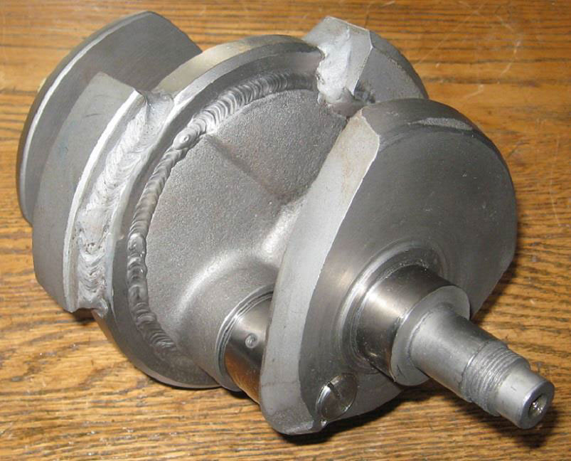
Balanced Triumph crankshaft. Outside diameter of counterweights is ½” smaller then a stock Triumph crankshaft’s flywheel.
BSA Crankshafts
Having owned many A65s I find that BSA motorcycles vibrate more than any British twin so going from a short stroke 3600 crankshaft to 900 offset is a huge improvement. There are also lots of good, straight, undamaged BSA A65 cranks to choose from but there are no more A10 cranks to build 84mm stroker engines (I have two left). The process is consistent and the result is immediately noticeable; a smooth motorcycle that accelerates quickly, is easy to start, has a unique Ducati-like sound and can be customized with different balance factors for road or racing.
One variation with this crankshaft that causes machining problems is the timing side journal. Various different bearings are used with either a 30mm, 32mm or 35mm journal as well as an oil feed quill that must be installed and ground so it is concentric with the crankshaft.
At this point I suggest to Customers that are building BSA engines to not do the timing side conversion. My nitrided cranks do not wear the bushing likes a stock crank does. The difference in the hardness of the crank and the stock BSA bronze timing side bushing follows standard bearing practice (a hard shaft and softer bushing) so wear is reduced. Reduced crankshaft flex also means bushing does not wear as quickly. For race bikes, spend the insane amount of money for the timing side conversion but for most BSAs a good modern oil pump, with an oil filter, will make the engine last just as long. My Australian customers do not do the timing side conversion even with 91mm stroker crankshafts.
BSA crank with stock timing side journal
Norton Crankshafts
Norton crankshaft should be easy to build but every Norton crankshaft I have ever found has been damaged or bent in some way. These crankshafts use a new flywheel that is machined from 4140 alloy steel with oil cavities that match the crank halve cavities with a hole drilled between them. These cranks can also be built using stops which may be used when building a 3600 crankshaft (I sell these too). The process starts with checking the crankshaft for straightness before they are taken apart. In many cases crankshafts from running Norton engines have their timing and drive side journals misaligned by up to .010”.
I still have to grind many of these cranks then heat treat them. Some require hard-chroming the drive and timing side journals to ensure that alignment is correct. Norton cranks are the only ones that bend during the nitriding process too which points to the quality of the material used when casting the Norton crankshaft halves. They can be straightened even after heat treating.
Two types of flywheels are used for Norton cranks; one that is a full-circle and one that material removed from each side. I see various articles about people building Norton cranks that weigh as little as 16 pounds but also note they break them. My lightest Norton crankshaft, after balancing, is 18.5 pounds using billet alloy aluminum connecting rods and light-weight forged pistons. A similar crankshaft with steel connecting rods weighs about 19 pounds. Both are smaller in diameter then a stock crankshaft by ½”. Stock cranks are 24 to 25 pounds.

Balanced lightweight Norton crankshaft. Note location pin for indexing crank half.

Full Circle Norton flywheel

Lightweight Norton Flywheel with one counterweight
Billet Crankshafts or Welded?

Billet crankshaft grain structure
Philosophy versus science comes in at this point. I would challenge any builder of an offset billet crankshaft, of a similar weight to my crankshafts, that a welded and heat treated crankshaft is just as strong, and may be stronger, then a billet crankshaft. I will even supply a crankshaft to test this.
First, billet crankshafts, are made from many strong alloy steels but the machining process they use cuts through the grain of the billet stock. Any material that flexes at a stress point, that has a grain that has been cut, will break at this point. People that we know, who will not be mentioned in this article, have broken billet cranks racing at Daytona and other similar high-speed long tracks. They have one of my crankshaft but an early one that was not heat treated.
Forged crankshaft where grain structure follows the shape of the crankshaft
A forged and heat-treated BSA or Triumph crankshaft, even a stock one, will always be stronger than a billet crank for a couple of reasons. One is the strength of a forging. Secondly the way that BSA, Triumph and Norton made their crankshafts using large hollow sections. Lastly, with BSA and Triumph offset crankshafts, the heat-treated spacer and centre section.
When a crankshaft is nitride heat-treated the hard surfaces on the inside and outside gives the crankshaft even more strength. This is something that can’t be done with typical carbon case-hardening. The crankshaft then becomes like a thick-walled hardened tube with large diameter hard surfaces on the inside and outside that do not flex as much as a stock crankshaft.
Laminated centre section
British crankshafts were designed to flex. The alloy steels of the time, similar to 4140 steel alloy, can tolerate a certain degree of flex like a spring without failing. Modern billet materials, such as expensive 86XX alloys, flex in a similar way but are not designed for this use. They are great for making a well-supported (3 or 4 bearing) automotive crankshaft, a camshaft or a large gear for mining machinery but are not used in applications such landing gear or other high-stress shafting where they are transitions in size between small diameters (the shaft and its journals) and large diameters such as flywheels.
Figure 23 – Laminated centre section
When I build an offset crankshaft, with its centre spacer plate, I create a stronger mid-section when the crankshaft is heat treated as the edges of the spacer plate, the cut surfaces inside the flywheel and the exterior surface are all heat treated. The nitriding process hardens every surface where the ammonia gas can penetrate including the ¾” diameter inside surfaces of the oil galleries inside the big-end journals. The interior of the oil feed gallery from the timing side is also hardened as well as the inside bore of the 7/16” hole tapped on the drive side of a Triumph crankshaft.

Drive Shaft Radius problem
One other problem that all billet crank manufacturers that I have seen on the web replicate is one of the major faults inherent in all British crankshafts; the small radius used on the drive side shaft between the shaft and the crank cheek. This is a big problem with Norton crankshafts that are long. Out-rigger bearings are installed on the ends of these shafts to fix this weak point.
This tiny radius is typically .030” when it can be as large as .080” or .090”. The radius used for the ID of the drive side bearing is .10”. Standard Norton Combat cranks would probably not be breaking at this point if they had had a large radius like this. This area can be welded then ground with the drive side journal to obtain this radius on racing crankshafts without needing an out-rigger bearing on the end of the long drive shaft.
Figure 24 – Drive Shaft Radius problem
I suspect, but can’t prove, that most billet cranks that are made for use in British twin cylinder motorcycles, which are based on 1930s and 1940s era designs, have not been designed by an engineer with experience in materials science and mechanical engineering for internal piston combustion engines. They replicate the design faults of the stock crankshafts! Many are probably amateurs, like myself, that have been lucky. So far no one has ever broken one of my offset crankshafts including strokers made from cast steel Norton crankshaft components running at 14:1 compression on methanol.
Camshafts
I always recommend that people purchase camshafts from Megacycle, Johnson Cams or Newman Cams in the UK. Megacycle and Johnson take from 6 to 9 months to make a custom offset camshaft $1000 USD. Newman takes about 3 months at about half that price plus shipping from the UK. All use new material when making their cams which I recommend for racing or long distance riding such as done by many customers in Australia.
I have made my own re-ground camshafts using the people at Canadian Chrome Plating and Crankshaft. I have also made BSA camshafts using 4140 material that is hardened to Rc40 then nitrided. The camshaft I make by re-grinding stock crankshafts take about 3 months to make using alloy steel that is also heat treated and nitrided.
The process they use for welding crankshafts and camshafts using a special flux that means welds are not cracked and have no air pockets. No TIG or MIG welder I have found is able to weld a crankshaft journal, or camshaft lobe, that does not include cracks after the surface is ground. The best fluxes for welding camshafts and crankshafts are unfortunately no longer available as they are carcinogenic.
An entire article can be written on making custom camshafts with the information I have learned over the past 19 years but that will be for another time.


Ignition Systems
First ignition system, four pickups. Boyer-Bransden systems are a late 1960s design and have limitation due to their advance curves and the type of pickups they use. Second ignition system, one pickup and modified rotor, Pazon and TriSpark systems are better. Testing a Dynatech system for a Sportster with different advance curves.
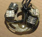
4 Pickup ignition system
Fixtures, tooling and instruction are still available for people to modify Boyer systems as they are inexpensive and you can find many spare parts, such as pickups and ignition units to build a four pickup system, at swap meets. TriSpark makes the best system that I have seen for power and advance curve as noted by my Australian and New Zealand customers.
Gregg Kricorissian in Ottawa has tested the various Boyer systems I have made. He compares them to the performance of a magneto. The four pickup system is the best with its only drawback being that a good 180W alternator system is required to power it. This system uses 12V coils that are completely separate from each other.

Single Pickup ignition rotor
The single pickup system uses two 6V coils that are wired in series with a wasted spark firing on the exhaust stroke of one cylinder while the other fires the ‘live’ cylinder. Gregg reports that the spark on the drive side is weaker (the magnet on the 450 degree angle) but this can be fixed using better coils then are typically supplied for British motorcycles. The magnets must be screwed in place with the polarity in the correct way and the magnets and screws must be glued and screwed in place. Loctite is not advised on small screws as they will break before releasing if a change must be made.
Various customer have requested that I build an ignition system using a magneto. Because of the way these magnetos are constructed, using a two pole rotor, a Sportster-type ignition system would have to be modified in some way. No one is willing to fund this experiment and peak voltage of a two-pole magneto would not occur at the firing points used for a typical British offset crankshaft engine. If someone made a four-pole magneto, such as used for some older aircraft engines, then a decent offset crankshaft magneto ignition system might be possible.
Stroker and other Custom Crankshafts
Stroker cranks are usually made from Norton crankshafts or modified stock crankshaft such as a T100 (500cc +) stroker. Modified Norton crankshafts can be used in BSA (A10 and A65) engines, Norton and Triumph (T120 & T140) engines. I have made stroker cranks for BSA A65s from A10 cranks but these cranks are extremely hard to find in useable condition. I still have two A10 crankshafts on-hand.
I have also gone in the opposite direction making an 80mm stroker Norton crankshaft using a three-piece Triumph pre-unit crankshaft that has had the journals welded to the 1-3/4” Norton size.
When building stroker cranks for Triumphs and BSA’s I had originally found problems in getting the connecting rod lengths correct. It seems simple, you can buy a 6” Norton rod to use for a BSA engine and a custom rod from MAP and others for a Norton crank stroker conversion. This leaves out T140 engines and creates problems with compression ratios. Going from a stock 82mm Triumph stroke with 9:1 pistons to the Norton’s 89mm stroke means using 8:1 pistons resulting in a compression ratio over 9.5:1. Not a problem with T120 barrels, or with 750 barrels on a T120 engine, but it causes problems if the barrels are bigger or are shorter like a T140.
SRM makes large barrels for stroker engines using a 6” connecting rod. They supply the pistons at the right compression ratio and machine the deck height of the barrels to match 84, 89, 90, or 91mm strokes.

Triumph stroker crankshaft
One of the other difficulties in building stroker cranks is the different journal spacing, crankshaft width and journal width. Most strokers use donor Norton crankshafts so that type of connecting rod is used. This change is simple to accommodate when the cranks are split and welded back together but the spacing of journals must still be checked by the crankshaft grinders against a stock, un-modified crankshaft.
To top the entire process off new splines may have to be machined, new keyways, new threads and with BSA stroker engines, new left-hand threads. Crankshaft seals may also have to be changed.
Figure 29 – Triumph stroker crankshaft
There are always a few people that want to build a stroker pre-unit Triumph engine. This causes two major problems; the first is that connecting rods may not fit in the cases and the oil scavenge pipe is in the way. This requires the machining of a new scavenge system. The second problem is that pre-unit Triumph crankcases may be able to handle a drop-on 750 kit but will be ripped apart by a stroker crankshaft with a similar 750 kit. A 93mm stroker crankshaft will fit in a Triumph T140 crankcase but this means that connecting rods are around 5.85” long when longer rods, such as the T120 type barrels with 6.25” connecting rods are preferred, in a large bore engine.
Everything possible must be done to not to use a stroker plate. This changes rocker ratios unless custom length pushrods are used. This is easy to do with a Triumph with its straight pushrods of equal length but hard to do with a BSA or a Norton. If building a stroker Norton it is best to use custom connecting rods that are shorter then stock to match the increased stroke (up to 93mm) using a connecting rod that is 5.875” long compared to the stock 6” Norton connecting rod.
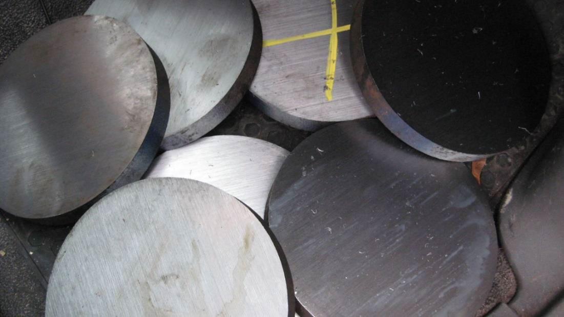
Norton crankshaft flywheels cut from 7” diameter 4140 steel for stock Norton and Triumph stroker crankshafts. Finished flywheel is 6.8” in diameter.

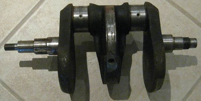
BSA crankshaft with counterweights before welding

Restored 1967 Triumph Bonneville with 900 offset crankshaft using Megacycle cams. Faster off the line then a stock T140 and as smooth as an air-head BMW.